Latest Products
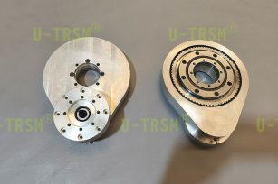
We keep on updating and iterating our products, optimizing the structural design and creating a more scientific and reliable slewing drive device.
-
 Lightweight design and performance of U-TR...
In the field of high speed automated mechanical equipment, the performance and light weight of the core drive compone...
Detailed instructions Send mail -
 Analysis of lightweight double gear slew d...
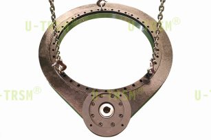
Core Design Advantages In response to the core demands of limited installation space for automated rotating pl...
Detailed instructions Send mail -
 Selection and characteristics of slewing d...
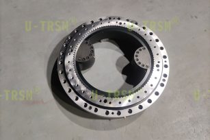
This slewing drive is used in automated mixing equipment. The customer requires that it rotate in the same direction ...
Detailed instructions Send mail -
 Analysis of the high speed rotating double...
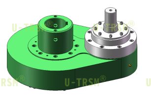
This double row ball gear type slew drive is used in automation equipment. The customer requires ultra-high speed ope...
Detailed instructions Send mail
What is the impact of gear displacement design on transmission performance?
Publish time:2024/07/08 News Views:289
In the process of designing the slewing drive structure, U-TRSM usually uses the meshing of large and small gears to transmit power and torque, and in some cases it is necessary to achieve the ideal requirements through the gear displacement. Through the reasonable displacement design, can achieve the effect of reducing the tooth surface contact stress, and can solve the noise and vibration and other problems, so as to improve the transmission efficiency and service life. So today, let us discuss what impact the reasonable displacement design of the gear will have on the transmission performance.
1. Appropriate positive displacement can increase the tooth root thickness, thereby enhancing the tooth root bending strength and improving the gear durability, which is most suitable for gears that need to withstand high loads or impacts.
2. By adjusting the displacement coefficient and tooth height, the tooth surface contact stress can be reduced and the meshing loss can be reduced, so as to improve the transmission efficiency.
3. Proper negative displacement can increase the gear mesh rate and helps reduce noise and vibration.
4. Improve the gear mesh state, increase the coincidence degree, improve the mesh smoothness, etc. The increase in the coincidence degree can improve the transmission continuity and smoothness, and reduce failures and damages caused by poor mesh.
5. The geometry of gears can be simplified through reasonable displacements, reducing machining difficulties and manufacturing costs.
6. For equipment that operates for a long time or bears high loads, the equipment service life can be extended by measures such as reducing wear on gears, improving strength and transmission efficiency, and using reasonable displacement.
7. The gear displacement increases design flexibility and through displacement can meet different center distance requirements or adjusting the gear tooth height to meet specific ratio requirements.
The U-TRSM design engineers have rich experience in designing and manufacturing slewing drives. Under different application requirements and working conditions, different gear transmission systems require different displacement methods and parameter settings, and in the design process, it is necessary to comprehensively consider various factors and carry out detailed calculations and simulation analyses to ensure the rationality and reliability of the design.
- Simple Analysis Of Factors Affecting Trans...
- What matters should be paid attention to w...
- The importance of grease to spur gear slew...
- What are the advantages of using planetary...
- Deformation control of slewing drive housi...
- Decibel wars – precision manufacturi...
- How to improve the torque of worm gear and...
- U-TRSM: innovators and practitioners in th...


